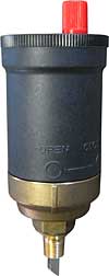
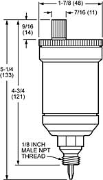
Automatic Air Vent (P/N WH-AV125-SO) purges air from high pressure mains and equipment in hot or cold closed water systems.
The vacuum break on the bottom of the valve prevents an air lock from forming and encourages air to be released from water. The air vent can be fitted anywhere in the positive pressure side of the system where air is likely to be trapped.
Air vents should always be fitted in an accessible area, which can be seen and serviced easily. |
Inside the automatic air vent there is a float which operates a lever according to the water level. When there is no water in the housing, then the float opens the valve. Air can therefore be vented from the system during filling. When the system has been filled, the inflowing water closes the valve and the vent is shut off.
Water usually contains oxygen which bubbles off during operation of the system and collects at the highest point. The automatic air vent must therefore be fitted at the air collection position.
The closing force of the float valve is very small and therefore waterborne dirt can prevent the valve from fully closing, which results in the valve dripping slightly. Expanding discs are built into the valve to prevent this dripping from occurring. These discs expand when wet and then shut off a secondary valve, thereby preventing leakage. |
 |
| |
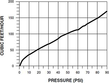
| NOTE: Flow capacity indicated is for an automatic air vent with the red vent cap correctly installed and operational. Additional capacity may be obtained by removing the red vent cap and installing a connection between the vent discharge and the drain using a Safe Waste Connector (sold separately). |
|